NEWS FLASH - March 2020 As you will understand, with the Covid-19 pandemic shutting down most normal business, we are not able to despatch orders for the time being. Thank you for your patience. We shall resume operations as soon as we possibly can.
Brightspark Magnetos
NEW ...
Take a look
at some of the equipment we use in our workshop for magneto servicing
and overhauls.
Affectionately known as the 'DB' (or dog's bollocks),
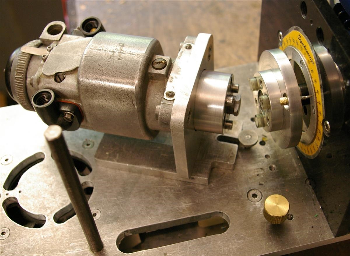
the rig pictured above has evolved over a long time and enables us to conduct cold and hot running tests on magnetos, dynamos
and magdynos. It has a main platform on which the machine under test can be
mounted, directly or using various spacer plates or mounting brackets.
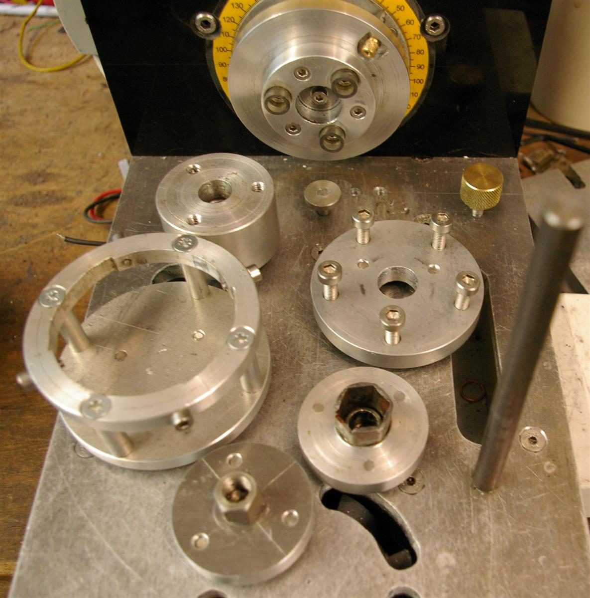
The DB rig's motor has various drive adapters for
coupling to the machine under test.
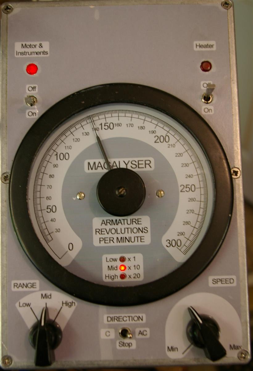
There are controls for
driving the motor at adjustable speeds (up to 6000 rpm) in either direction and
a tachometer for indicating the speed.
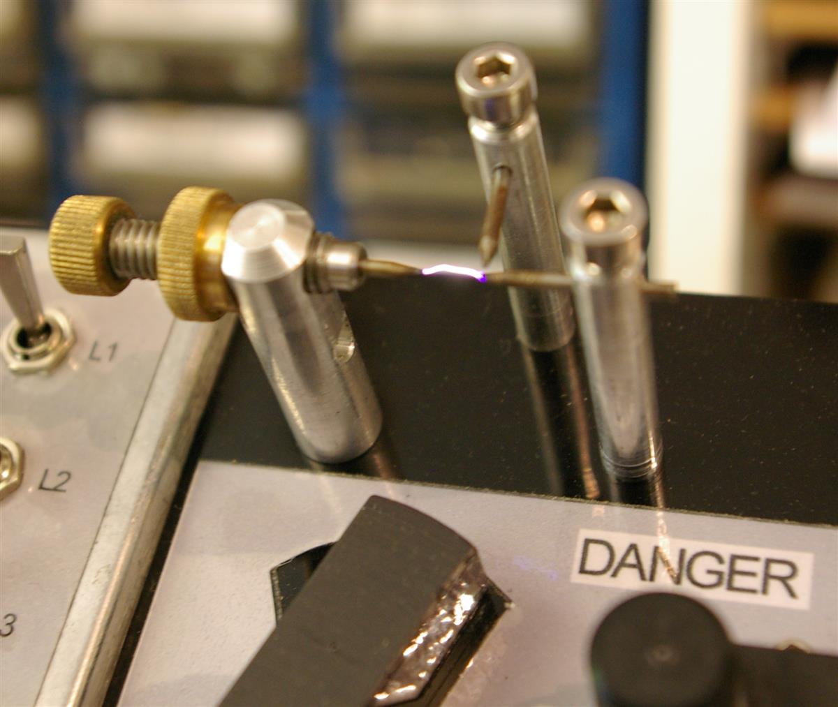
For magnetos, we have a variety of different types of spark test gap to which the
HT output(s) of the magneto can switched.
Above is one of a pair of 3-point gaps. The gap between the main electrodes
is typically set to 5.5 mm (as specified by Lucas for slow-running tests of their post-war
magnetos). The 3-point gaps are the best way of reliably
testing the slow-speed performance of a magneto. However, they do require
regular attention to the sharpness of the electrodes.
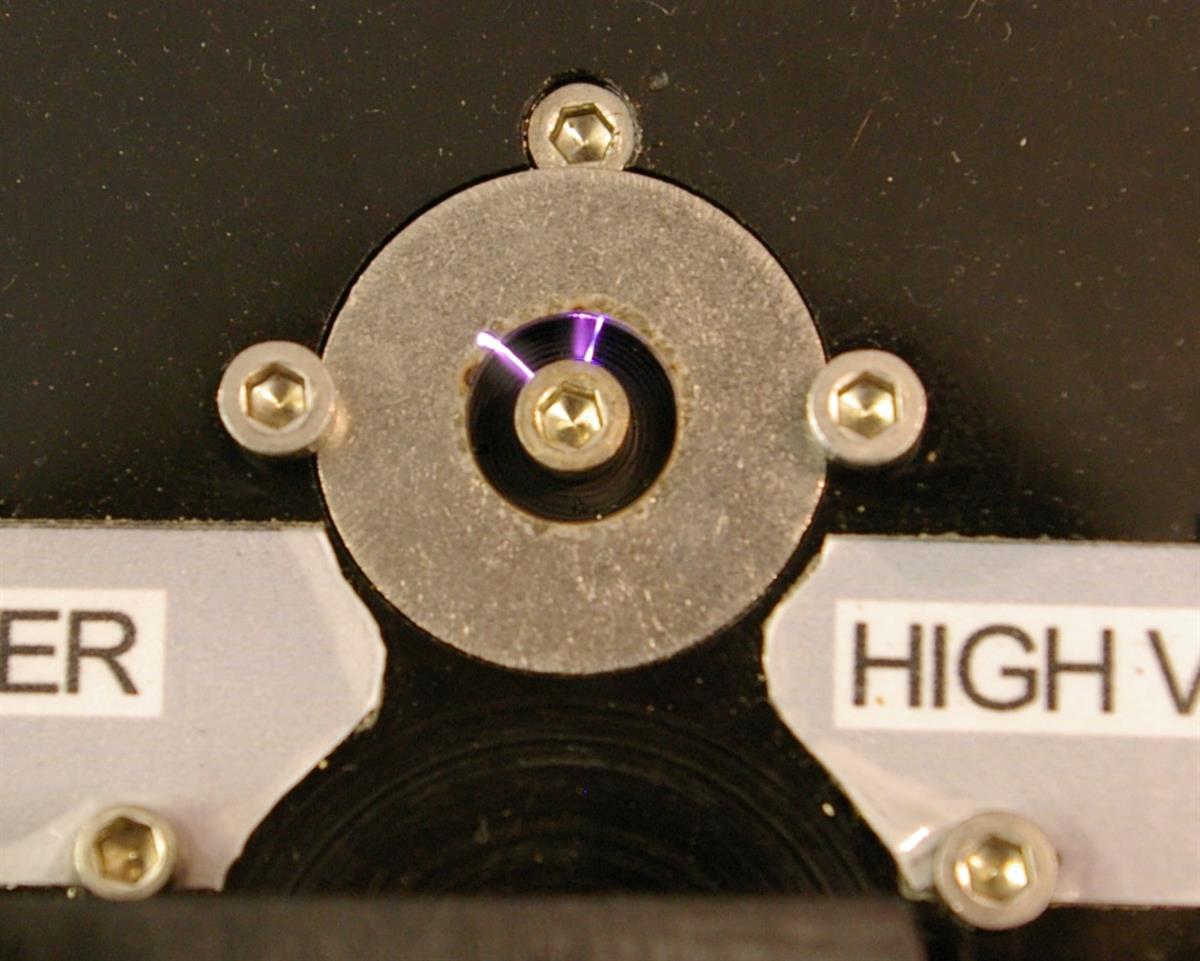
The DB rig has an
annular gap. This is particularly good for prolonged high-speed
testing of a magneto. We can fit rings with different internal
diameters to vary the nominal voltage at which the gap discharges.
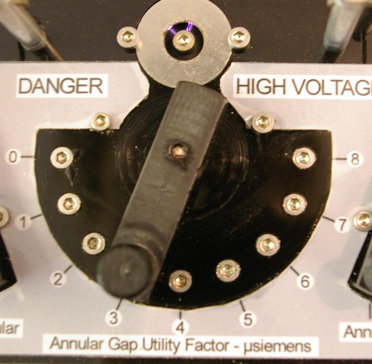
The annular gap can be
used with a 'utility factor' circuit that lets us switch in various
slightly-conductive loads in parallel with the annular gap to simulate sparking plugs
with various degrees of fouling. (E.g. 4 microsiemens = 250,000 ohms.)
(Click play button to view video clip.)
The DB rig also has a rotary gap. As you'll
be able to see in the video clip, this lets us check the relative timing of the two sparks of
a twin magneto.
(Click play button to view video clip.)
We can drive Lucas and BTH magnetos through
their ATDs. The DB rig's rotary gap and tachometer therefore let us check
the ATD characteristics and, if we want, plot the
advance curve of the ATD.
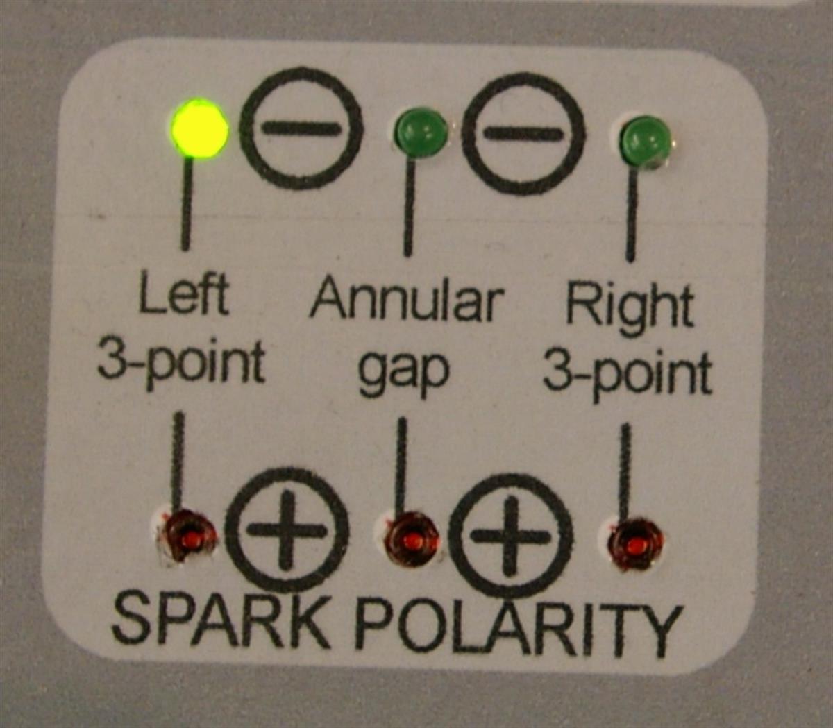
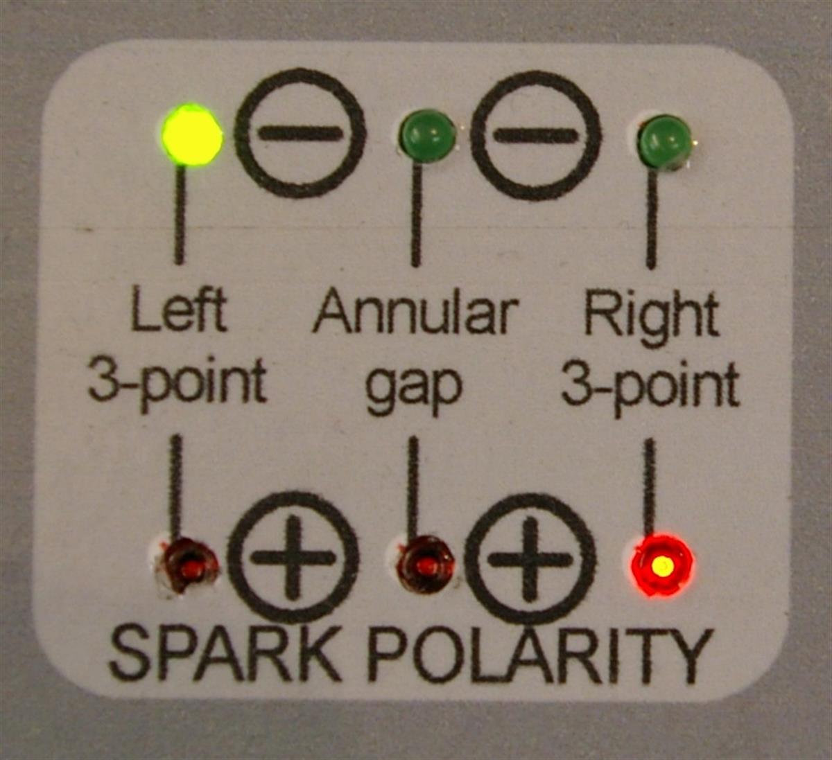
There are indicators for showing the polarity/ies of the HT output(s).
With a magneto for a single-cylinder engine, the output has a single
polarity (positive or negative relative to ground/earth). Negative
polarity is preferred with a single magneto, because the negative HT output goes to the central electrode
of the sparking plug, which runs hotter than the earth electrode. Sparks
jump from negative to positive. Due to the thermionic effect, a spark can
jump more easily from a hotter electrode to a cooler electrode than the
opposite way round. The polarity
of the spark can be swapped if necessary in many ways, the simplest usually
being to flip the polarity of the magnet.
With a magneto for a twin-cylinder engine, one HT output should
be negative, and the other positive. However, if the insulating part of the
slip ring track has become caked with carbon (e.g. from pick-up
brushes that are too soft), it is possible, when the magneto is running on an engine, for a
negative spark to go to the positive sparking plug and vice versa. This is
because the HT current may find it easier to track around the caked-up
carbon on the insulation of the slip
ring and jump the gap of the sparking plug in the incorrect cylinder (which
is on its exhaust
stroke and therefore at relatively low pressure), rather than go direct
to the gap of the sparking plug in the correct cylinder (which is on its compression
stroke and therefore at relatively high pressure and more difficult to fire). The result is a misfire.
Using the polarity indicators and the pair of 3-point test gaps on the DB rig, we can
detect this, even at very high speed, by reducing the size of one of the
test gaps, and seeing whether that then gets sparks of both polarities.
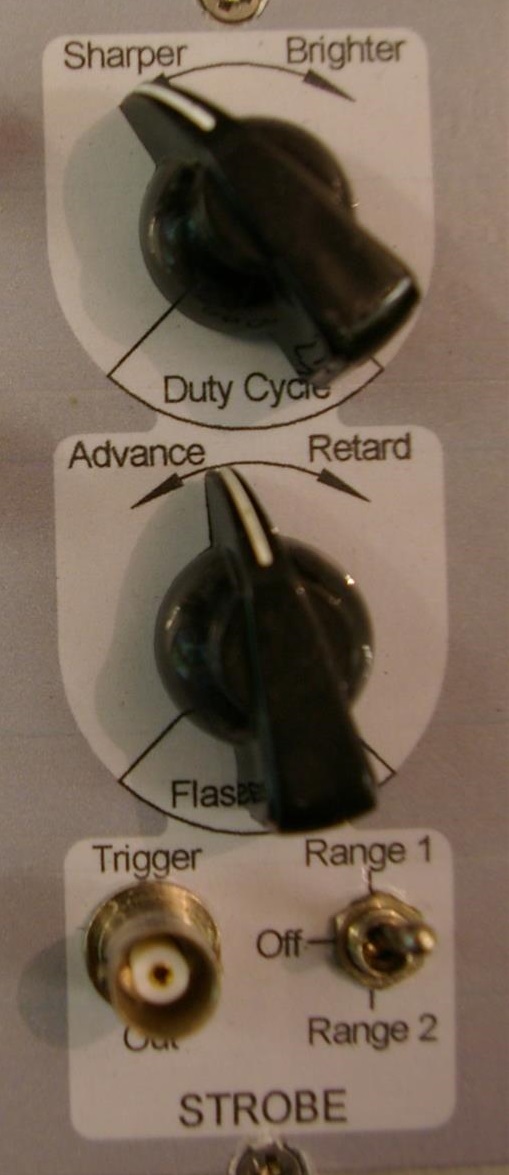
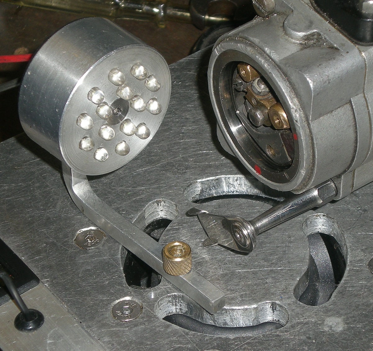
A strobe lets us freeze the view of the magneto at any
position of the armature and at any speed. This is particularly useful for
investigating problems with the contact breaker assembly, such as points
that jitter as they begin to open (e.g. due to a sloppy pivot). The strobe
controls let advance and retard the strobe flash point, and also adjust the
balance between brightness and sharpness of the view.
(Click play button to view video clip.)
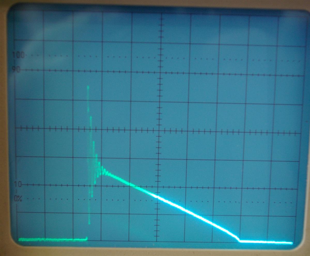
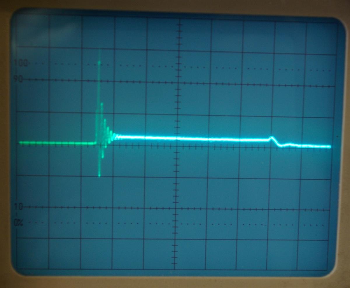
HT current
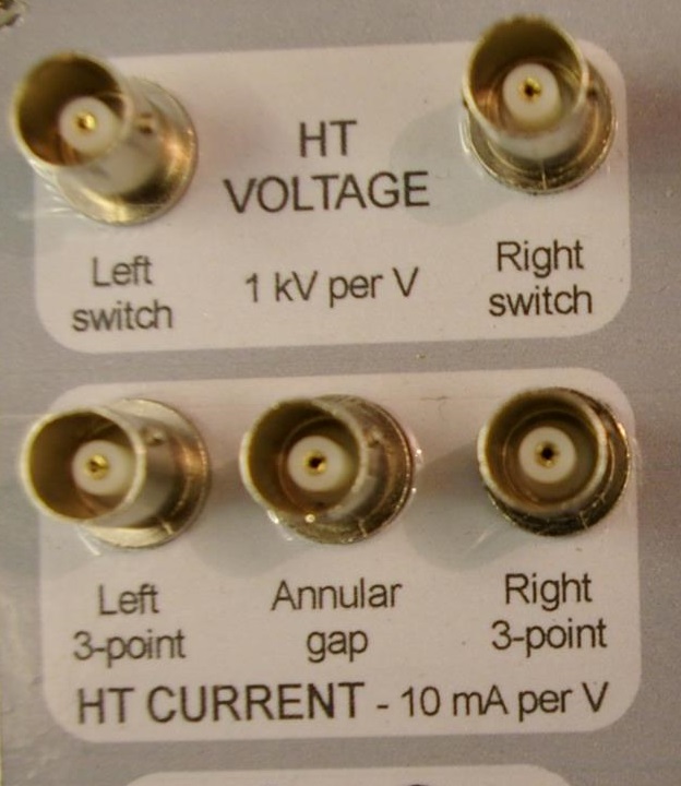
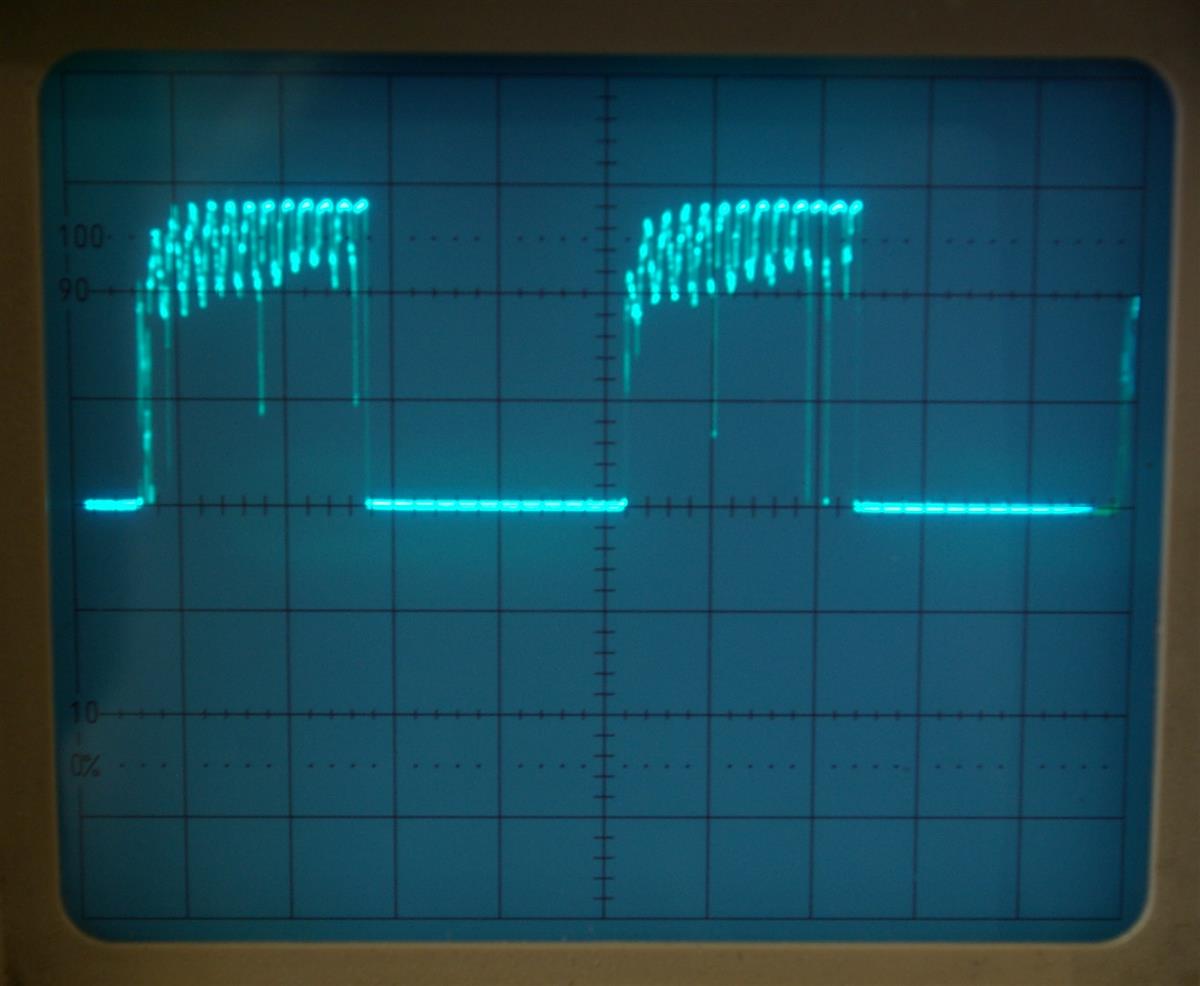
Oscilloscope outputs let us view
the LT and HT voltage and current waveforms.
LT voltage
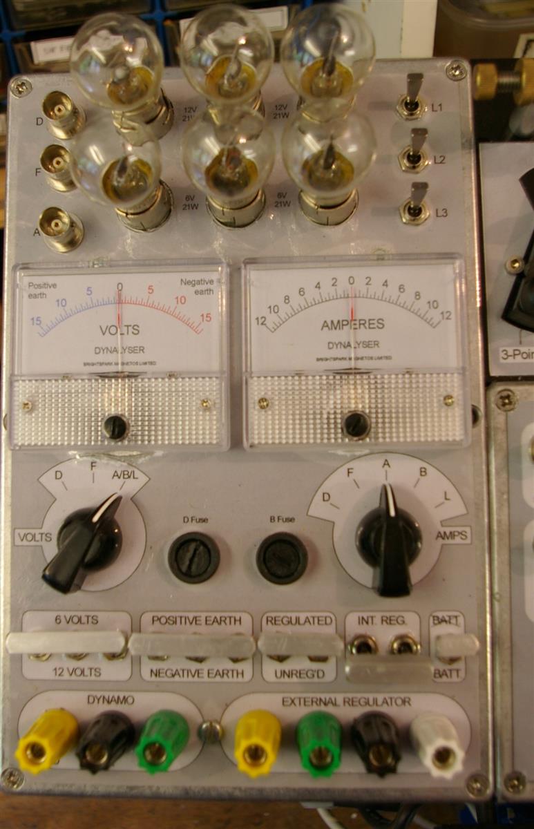
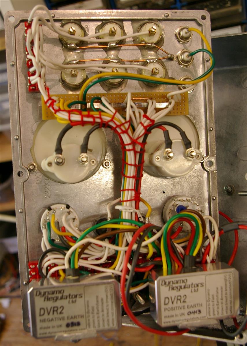
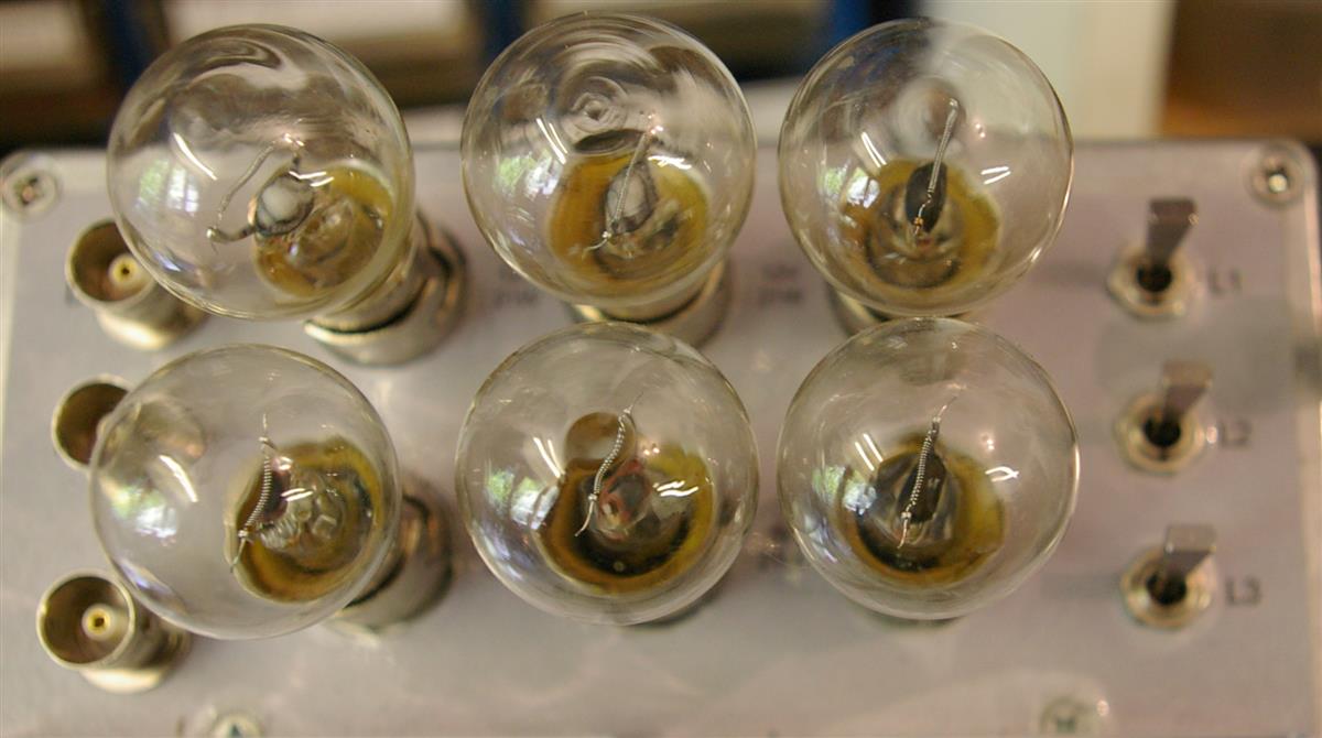
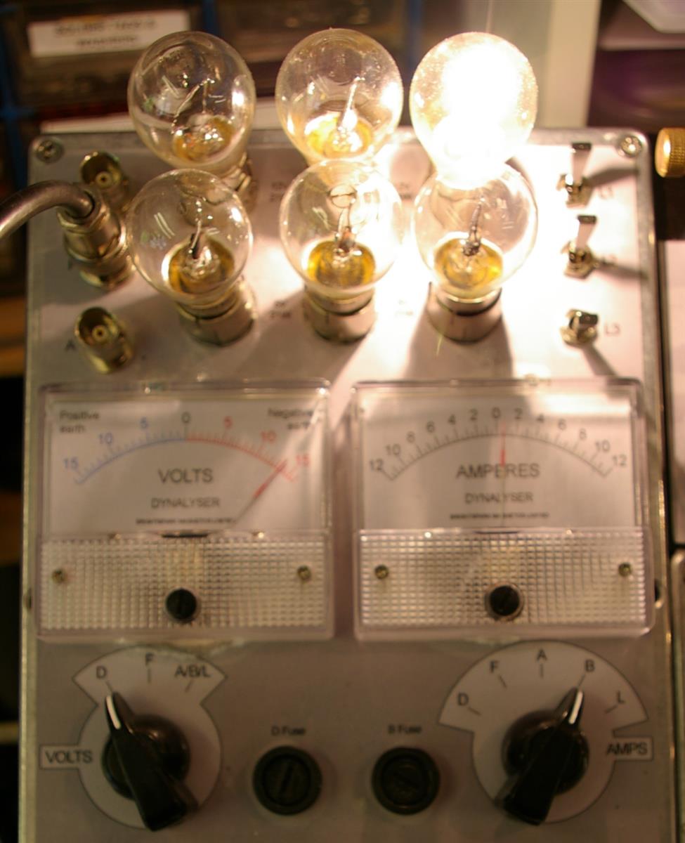
For dynamos, the DB rig has what we call a 'Dynalyser'
unit. The Dynalyser has its own internal dynamo voltage regulators (supplied by
Dynamo Regulators Ltd) and
battery bank.
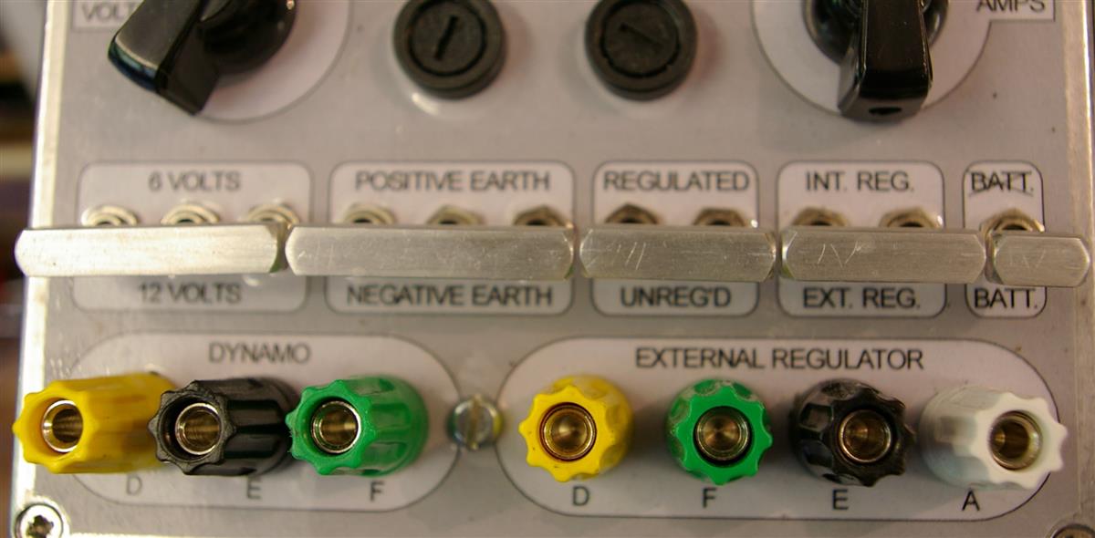
A switch panel enables us to:
●
'flash' the dynamo;
●
'motor' the dynamo;
●
test the dynamo unregulated;
●
test the dynamo using its own regulator; and
●
test the dynamo using the inbuilt regulators at:
◦
6 volts positive earth;
◦
6 volts negative earth;
◦
12 volts positive earth; or
◦
12 volts negative earth.
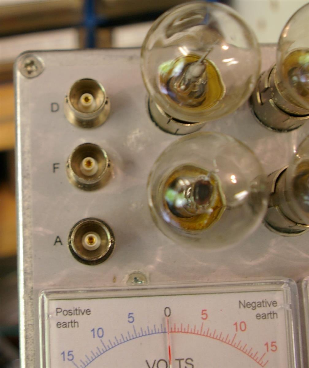
Various loads can be switched into circuit. A voltmeter can be switched to display the voltage of
the dynamo output 'D', the field
input 'F' or the regulator output 'A'. An ammeter can be
switched to display the D, F, A, load or
battery current. These are particularly useful for checking the operation of
a dynamo regulator over all of its three phases (cut-out, full-field, and
regulated) with various loads.
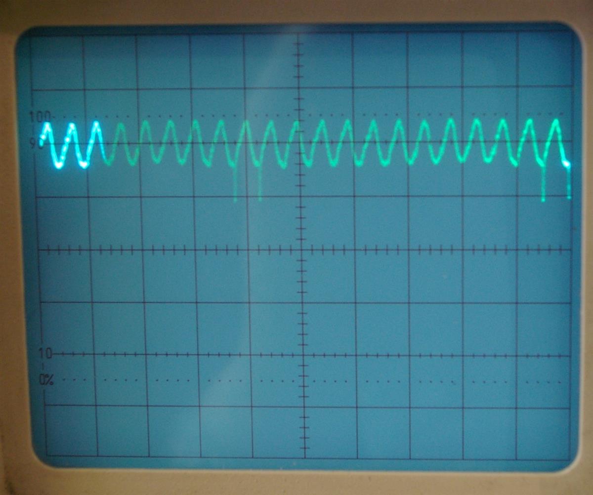
There are oscilloscope outputs so that the D, F or A voltage waveforms
can be viewed. For detecting faulty sections in a dynamo armature winding,
viewing the D voltage waveform on an oscilloscope is far simpler than using
a device such as a 'growler.' By viewing the field voltage waveform, we can
see how cleverly or idiotically various designs of regulator operate.
Dynamo D output voltage
Field F input voltage during the regulating phase
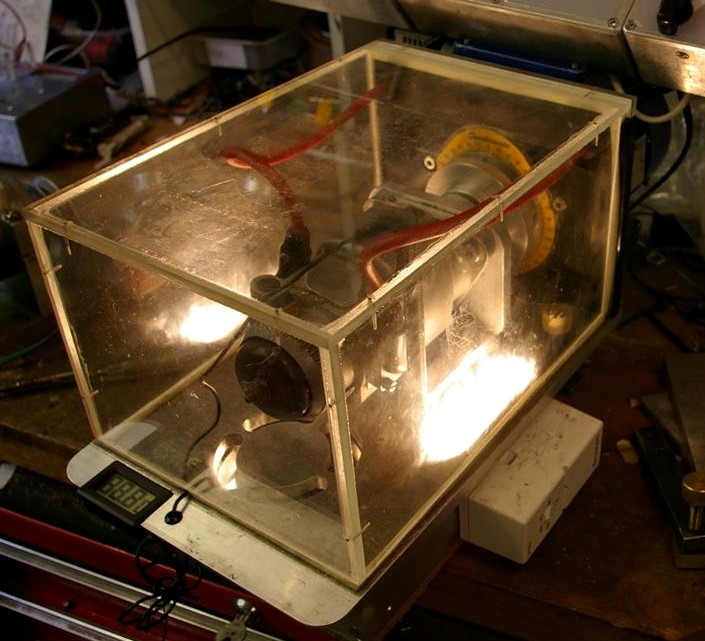
The DB rig has an
inbuilt 400 W heater, with circulating fan; a removable, transparent enclosure;
and a thermometer. We can therefore conduct any of the
above tests at elevated
temperatures. We usually test at temperatures up to 50°C,
which can be attained in about ten minutes, although it does take longer for
the heat to soak through to the centre of the armature. Sometimes we go up to
70°C. Many faults with dynamos and, more particularly, with magnetos appear
only when the machine is up to temperature. How many times have you heard
the complaint, "It won't start when it's hot"? It is therefore very important
for workshop tests to include hot testing.
 Brightspark Magnetos