|
|
Reassembling the magneto including fitting an EasyCap
|
|
|
Special tools/materials required
|
|
|
Procedure - generally
This section entails inserting
and removing the armature a few times. For magnetos that require an external
keeper while the armature is not in the main housing, ensure that the
magneto is in its keeper before you remove the armature.
Place the armature in the main housing and refit the end-housing and
the original shims for it if there were any. As the screws approach being
tight, check that there is end float and that it does not completely
disappear. The acceptable end float is between 0.001" and 0.005".
If there is negative end float, loosen the two screws until there is no
end float and no preload, and then use a set of feeler gauges to measure the
gap between the end housing and the main housing. You will then need either
to obtain/make and fit one or more end-housing shims and/or remove one or
more of the shaft shims that you may have fitted earlier. You can
use your feeler gauge measurement to calculate the required thickness to
achieve the desired end float. End housing shims are available in
thicknesses of 0.003" and 0.005".
If there is positive end float, try to assess how much there is.
You will then need either to remove one or more end-housing shims and/or add
one or more shaft shims so as to correct the end float.
Although the pukka end housing shims are of brass and are still
available, we have found that homemade shims of paper/card are perfectly
satisfactory. You can download a pattern for a standard K1F/K2F/KVF end
housing shim by
clicking here. It can be printed out at 100% scale on paper or card, cut
out and punched, and there you are.
Once you are happy with the end float, remove the armature, check
that there aren't any ferrous particles stuck to the magnetic pole pieces in
the main housing, apply a high-melting-point grease (such as Castrol 'LM') to the balls of the bearings, reassemble, and fully tighten the screws for
the end housing. The armature should spin freely.
Now clean, check the condition of, and replace the earth brush and
safety screws and, if appropriate, the manual advance and retard mechanism.
For the ring cam instruments, with the cam ring removed, apply some engine oil to the felt strip in the end housing and, if
present, the felt pellet in the ring cam. Then replace the ring cam,
ensuring that the notch with the square sides registers with the pin in the
cam housing. If manual advance and retard is fitted, also ensure that the
fitting at the end of the advance/retard cable registers with the V-shaped
notch in the cam ring.
|
|
 |
Turning now to the contact-breaker assembly, different procedures are
required for the different types of CB assembly. |
|
|
Ring
cam instruments (K1F, K2F, KVF and MN2) with the earlier brass contact
breaker back-plate
Remove the 6BA screw that is
holding the fixed point mounting block to the back plate. This will release
the mounting block, with the fixed point still attached. You will notice
that the screw you removed has a metal washer immediately under its head and
an insulating washer under that. Retain them. Also, the screw passed through
an insulating sleeve in the mounting block; that can stay there. Beneath the
fixed-point mounting block, there is a sleeve with a flange at its top end.
The sleeve passes through one or two insulating spacer plate(s) into the
central hole in the back plate. Remove them and separate the sleeve from the
spacer plate(s). The flanged sleeve will be reused, but the spacer plate(s)
will be replaced by the C01 or C02 EasyCap condenser.
You can now check the condition of the points surfaces and dress
them if necessary. If the moving point needs attention, it should be
temporarily removed by (a) swinging its retaining blade out of the way,
being careful not to lose the little plastic or fibre pimple that it bears
on at the pivot point, and (b) undoing the tiny screw that holds the end of
the arched spring to the moving point, being careful that the spring blade
does not ping the tiny screw into orbit.
You can also check the condition of the pivot for the moving point. If there
is any slop in it, it can cause bad running of the engine. A replacement
points set will, of course, come with a free pivot hole of the correct size.
The pivot post should have a diameter of 5/32" (0.156"). If it is
appreciably worn, it can be replaced, but that is a specialist job.
|
 |
 |
With the points clean and the moving point reconnected, now
reassemble all the other parts, but with the C01 or C02 EasyCap condenser in place of
the original insulating plate(s). So, the flanged sleeve passes through the
larger hole in the mounting plate of the EasyCap condenser from the
condenser side and into the central hole in the brass back plate. The fixed
point mounting block sits on the EasyCap mounting plate, with its fat end
over the flanged sleeve. The 6BA screw passes through: 1) the metal washer,
2) the insulating washer, 3) the parallel sleeve in the fixed point mounting
block, and 4) the smaller hole in the EasyCap mounting plate, before
screwing into its hole in the brass back plate. The contact breaker
assembly can now be fitted to the end of the armature, with the integral key
on the CB assembly engaging the keyway in the hole in the armature shaft.
Then insert and tighten the long centre screw. |
| |
Ring
cam instruments (K1F, K2F, KVF and MN2) with the later steel contact breaker
back-plate
Remove the screw that is
holding the spring anchor bracket and the fixed-point mounting plate to the back plate. You will notice
that the screw has a metal washer immediately under its head and
an insulating washer under that. Retain the metal washer. The insulating
washer will, however, be replaced by the C04 EasyCap. You will see that
there is a moulded nylon spacer between the spring anchor bracket and the
fixed-point mounting plate. Note which way round it goes.
You can now check the condition of the points surfaces and dress them if
necessary.
With the points clean and the moving point reconnected, now
reassemble all the other parts, but with the C04 EasyCap condenser in place
of the insulating washer with its capacitor elements uppermost as shown in
the picture. So, the screw passes through: 1) the metal washer,
2) the EasyCap condenser, 3) the spring anchor bracket, 4) the nylon insulator, and
5) the fixed point mounting plate, before
screwing into its hole in the steel back plate. The contact breaker
assembly can now be fitted to the end of the armature, with the integral key
on the CB assembly engaging the keyway in the hole in the armature shaft.
Then insert and tighten the long centre screw. |
 |
 |
Face cam instruments (MO1 and N1)
With
the moving point removed, undo the screw that holds the moving-point
mounting block to the back plate. It should have an insulating washer under
its head, and there should be an insulating sleeve in its hole through the
moving-point mounting block. There should also be one or more insulating
plates between the moving-point mounting block and the back plate, and a
flanged insulating sleeve that passes through those plate(s) into the hole
in the back plate for the centre screw. The insulating plate(s) will be
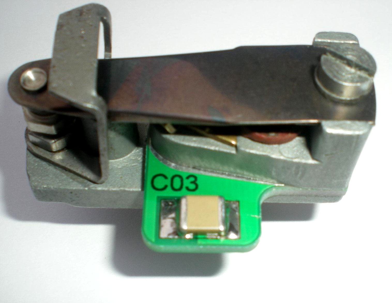
replaced by the C03 EasyCap. You can now check the condition of the points
surfaces and dress them if necessary.
With the points clean, reassemble all the other parts apart from the
moving point, but with the C03 EasyCap condenser in place of the insulating
plates between the moving-point mounting block and the back plate as shown
in the picture. The plain insulating sleeve and the flanged insulating
sleeve should both be reused, with the flanged sleeve passing through the
larger hole in the EasyCap into the hole in the backplate for the centre
screw. Check that the tappet is still in place, and apply a few drops of oil
to the wick opposite the tappet on the underside of the back plate. The contact breaker
assembly can now be fitted to the end of the armature, with the notch in the
end of the armature shaft properly engaging with the CB assembly. Insert and tighten the long centre screw.
The refit the moving point. |
|
| |
Finally The points gap should now be adjusted to
the value specified by the engine maker. If the setting is unknown, use
between 0.012" and 0.015". Finally, replace the end
cover and the HT pick-up(s) having firstly checked that the brushes are in
good condition and that there are no signs of tracking on the HT pickups. |
|
| |
Next: Magneto re-installation |
|
|
 Brightspark Magnetos