|
|
Reconfiguring the MO1, MN2 and N1
|
|
|
Special
tools/materials required
-
Soldering iron (50W preferably)
and solder
-
Adhesive-lined heat-shrink sleeving, and a heat gun or other suitable
heat source for shrinking the sleeving
-
Possibly a small solder tag
|
 |
|
Procedure - overview
Having
partly separated the drive-end end-piece from the bobbin, you will be able to
see whether the armature is fitted with an original Lucas condenser
(picture top right) or with a more modern device which is usually
potted in resin. The procedures to be adopted are somewhat different.
Before proceeding any further, it is important that you mark the bobbin
and the armature end-piece at the CB end so that you will put them back
together the same way round. Also, work out and make a note of which
of the two wires coming from the bobbin is earth (i.e. going to the
bracket/tag screwed to the end piece) and which is live (i.e. going to the
tag on the condenser which is not earthed).
|
 |
Procedure - if fitted with original Lucas condenser
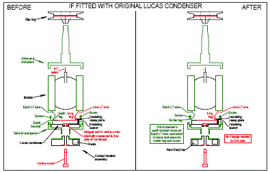
The thumbnail of the 'before-and-after' schematic on the right illustrates what is required.
Click on the picture to see a clearer printable Acrobat file.
In detail, you need to unsolder the bobbin wires from the condenser so as to
free the end-piece and condenser from the remainder of the armature.
Then
remove the condenser from the end-piece by undoing the two small screws,
noting how the insulating clamp plate and the insulating strip fit, and
which way round the condenser was fitted.
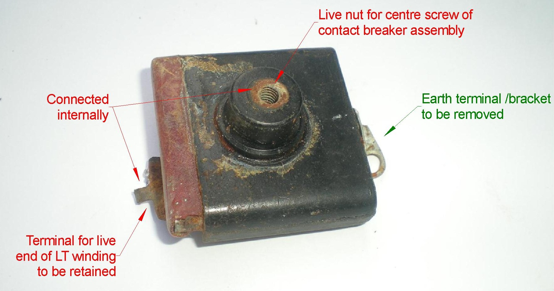
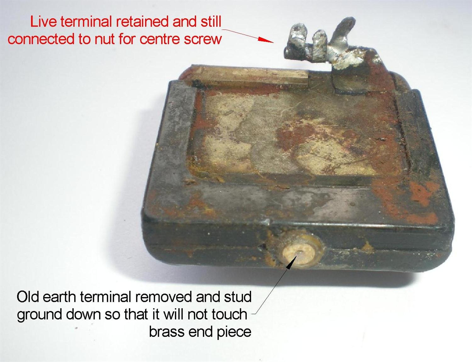
Then tear off the earth bracket and grind or file down the stud to which the
earth bracket was attached, as shown in the picture to the left.
|
 |
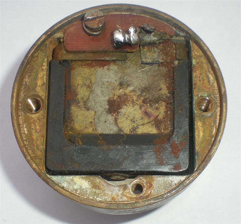 |
Fit the old condenser back into the end-piece, the same way round as before,
and check that the remains of the earth stud will not touch the end-piece,
as shown in the picture to the right.
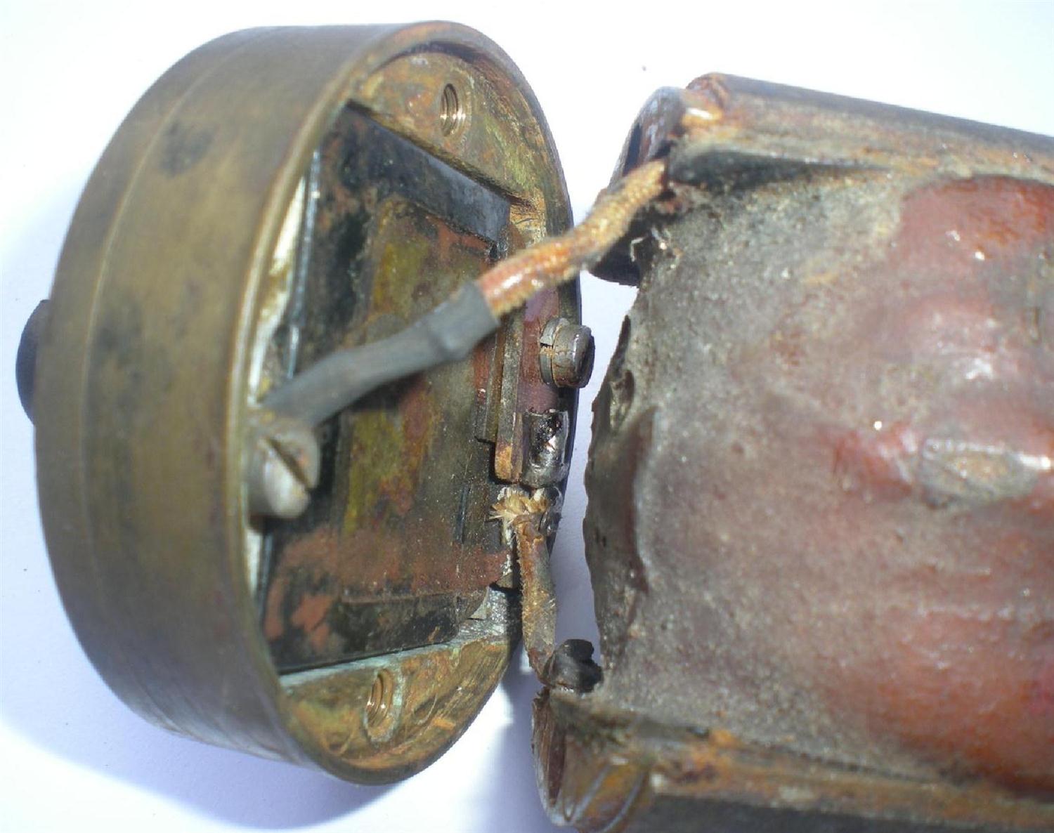
If the integral nut for the centre screw looks rusty (as in the photo at the
top of the page), clean it up with a 3BA tap, if available.
Solder a solder tag to the end of the bobbin's earth wire.
Re-solder the bobbin's live wire back onto the live terminal of the
condenser, making sure that nothing on the live side can short to the brass
of the end-piece or the adjacent condenser fixing screw.
|
|
Now screw the solder tag on the earth wire into the position where the old
earth bracket used to be, as shown in the picture to the left.
Then reassemble the end-piece with the bobbin, and refit the two long
through-screws. Tighten them fully and then release them slightly.
You can now measure the LT and HT resistances again and check whether they
are unchanged from the figures you obtained earlier. Make a
note of the HT resistance.
|
 |
| |
Next: Reassembling armature |
| |
Procedure - if fitted with a non-original condenser
The original Lucas condenser also provides the nut for the contact-breaker
centre screw. When a non-Lucas condenser was subsequently fitted, some
method would have been adopted to provide a nut for the centre screw. Also,
the new condenser may well have been potted in resin. It is impossible to
provide any detailed instructions without knowing what is there at the
moment.
|
|
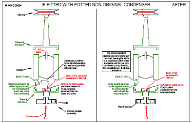
However, the thumbnail of the 'before-and-after' schematic
on the right illustrates
generally what is required. Click on the picture to see a clearer printable
Acrobat file. |
 |
| |
In summary, you need to:
-
retain the original method of providing a nut for the CB centre screw,
or provide some alternative which is insulated from the brass end-piece;
-
identify which is the earth wire from the bobbin and ensure that it
remains connected to the brass end-piece;
-
identify which is the live wire from the bobbin and ensure that it
remains connected to the nut for the centre screw without being able to
short to the brass end-piece;
-
disconnect at least one of the wires to the previous condenser (and
possibly remove it altogether) without affecting connections "2" and "3"
above.
Once that has been done, reassemble the end-piece with the bobbin, and refit
the two long through-screws. Tighten them fully and then release them
slightly.
You can now measure the LT and HT resistances again and check whether they
are unchanged from the figures you obtained earlier. Make a
note of the HT resistance.
|
| |
Next: Reassembling armature |
|
 Brightspark Magnetos