|
|
The 'Complete Works' condensectomy - splitting
the armature
|
|
|
Special tools/materials required
-
For all Lucas magnetos, and for
some other makes too, you will need a puller for removing the inner race
of the bearing next to the slip ring. You may also need a puller for the
slip ring if it is stuck. Drawings are available for
download here.
|
|
|
Procedure
Please note that the pictures below show the armature of a Lucas K1F, K2F
or KVF
magneto, which has the slip ring at the CB end and the condenser at the
drive end. For MO1, MN2 and N1 instruments, the slip ring and condenser are
at the opposite ends.
|
.JPG)
 |
|
You
need to
remove the inner race of the bearing
next to the slip ring, and the slip ring itself, from the
armature in order to access the heads of the two long screws that hold the
brass end pieces to the bobbin of the armature, so that the brass end-piece
containing the old condenser can be separated from the bobbin.
|
 |
You may find techniques described
on the internet for removing the inner race without any special
tools. However, with them, and on a K-series magneto especially, there is a
great risk of damaging the
CB-end brass piece and rendering it useless. Universal 2- or 3-legged
pullers are unsuitable for the job, because there is no space between the
inner race and the oil flinger into which the feet of such a puller can
engage. A special bearing puller is required; you can make
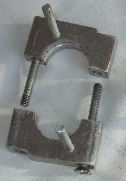
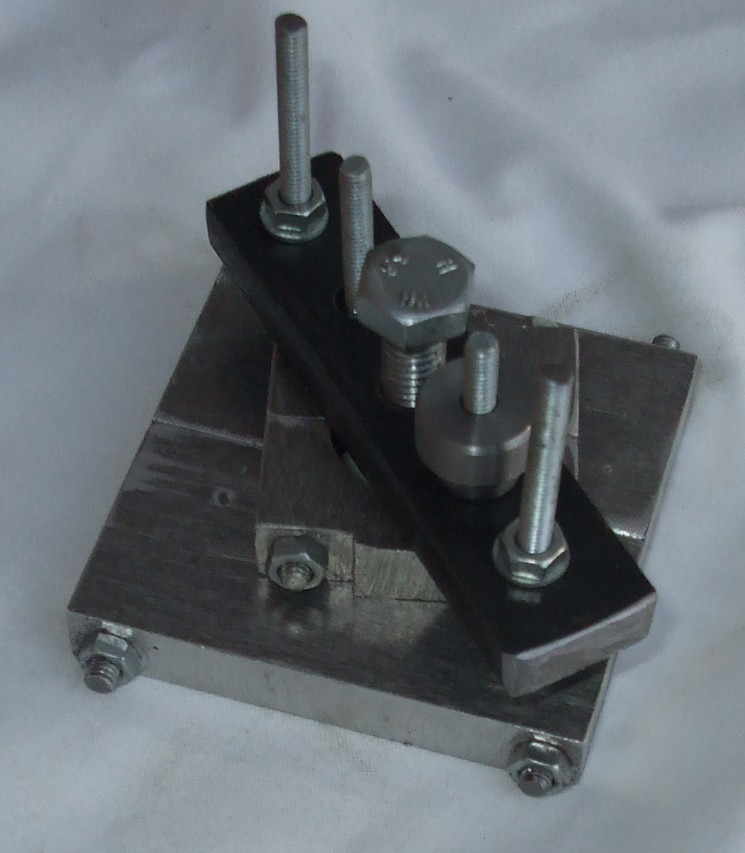
the required pullers shown in the photos from the
drawings which you can download by clicking here.
It is sometimes possible to remove the slip ring by hand without damaging
it, but it is far safer to use a special puller as is also shown in the
downloadable drawings.
|
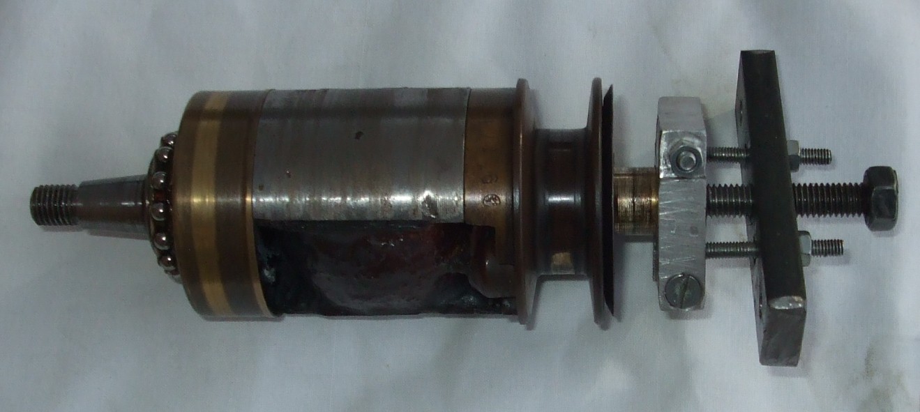 |
The clamp halves are secured to the inner race. The bridge is secured to the
studs on the clamp halves, with the end of the extractor screw bearing
against the cone which is placed in the internally-tapered end of the
armature. Turning the extractor screw draws off the inner race and the small
collar outboard of it. |
|
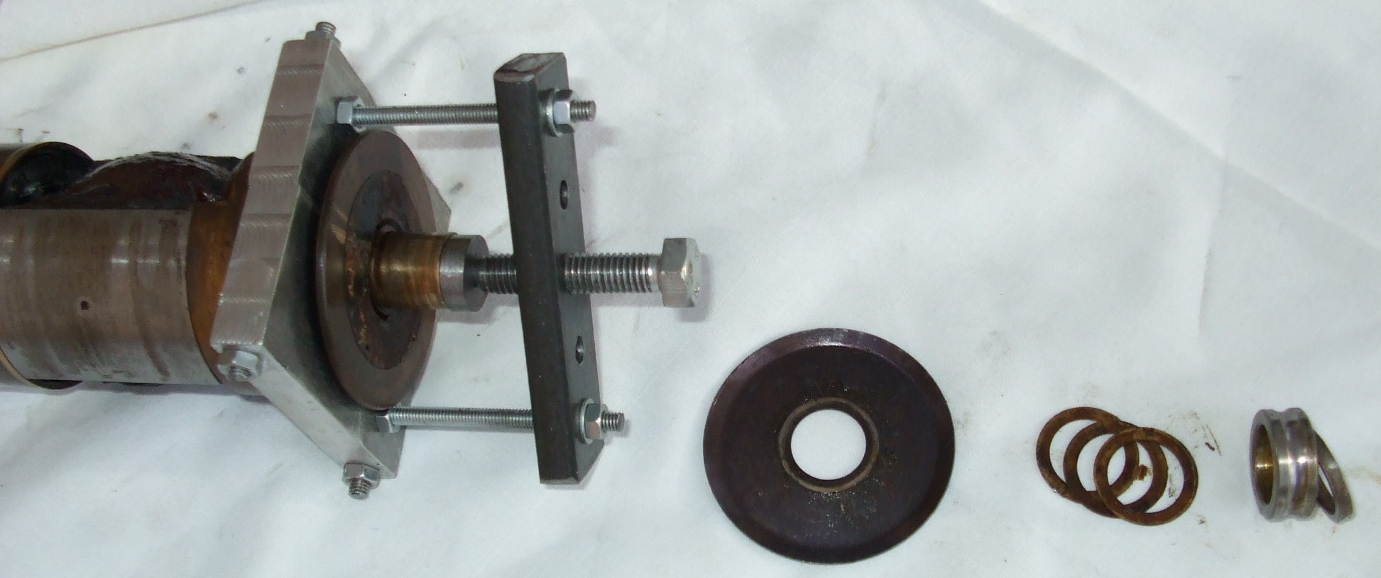
Possibly one or more shim washers can then be removed (note and keep safe),
as too can the oil flinger which prevents any oil getting onto the slip ring.
The slip ring can then be removed in a similar fashion using a
larger clamp. In the picture, note the use of the cone to protect the
armature shaft, as for the bearing puller. Often there is no need for a
puller, but in the case of original Lucas armatures which have never been
stripped, shellac can make extraction extremely delicate. |
 |
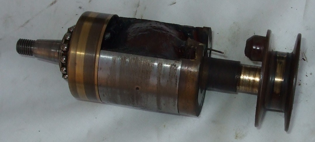 |
With the slip ring pulled, note the spike of the HT coil, which
fits into a very snug hole in the boss on the rear of the slip ring.
Take extreme care not to bend the HT
spike unintentionally. |
|
The particular slip ring in the
picture is in generally good condition, being neither broken on
its flanges (through being removed without the safety screws having been
fully withdrawn) nor heavily 'tracked' where the HT pick-up brushes have run
against it. It should be serviceable for a good while yet. A clean and
polish will be enough. In some cases, the lightest possible skim in a lathe is
recommended, or replacement in cases of deep scoring or any breakage. Chips
or other damage to the outer edges of the flange of a slip ring can cause
surprising amounts of spark-tracking when the magneto is working hard, and
should not be accepted. |
|
| |
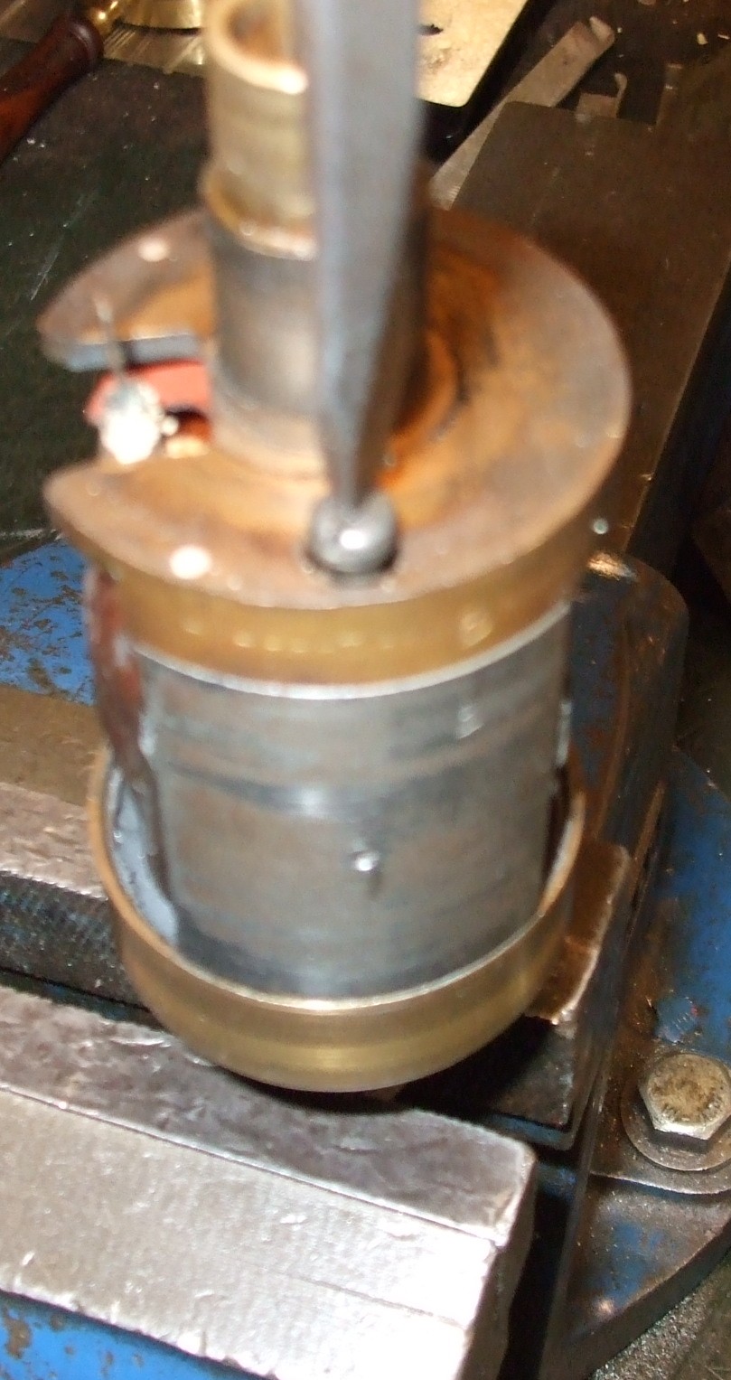
Unscrew the
two through-screws which hold the brass ends of
the armature to the central 'bobbin' - the laminated core around which the
low and high tension windings and their insulation are laid. Once you have
removed the screws, it is a good idea to put the slip ring temporarily back
in place so as to protect the HT spike. |
 |
| |
Before going any further, scribe or punch corresponding marks on
the bobbin and on the drive-end brass end-piece (but not on the track for
the earth brush) so that your can put them back together, later on, the same
way round. |
| |
Also, if you have an ohmmeter or multimeter, measure and make a
note of (a) the LT resistance between the earth brush track and the nut for
the CB centre screw (hidden between the bobbin and the CB-end brass
end-piece) and (b) the HT resistance between the earth brush track and the
HT spike. You should get readings of about 0.6 Ohms and 5000 Ohms. Anything
vastly different from these figures probably indicates that the bobbin needs
rewinding, although a lower figure for the LT resistance could be a result
of the old capacitor providing a short circuit. |
| |
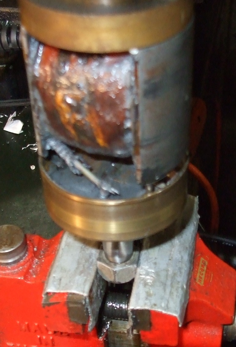
Then, the brass end-piece containing the condenser needs to be gently pulled from the
bobbin. At this stage you do not need to separate them completely, just by
about 5/16" (8mm).
Don't try to separate the other end-piece from the bobbin - all
being well, it can be left undisturbed.
|
 |
For K1F, K2F and KVF magnetos:
The drive-end brass end-piece and the bobbin are also connected by two
dowel pins, which are often quite tight.
Resist the urge to hold the drive-end brass end-piece in the vice. You
can, however, place a spare 3/8" BSF nut (or an interlocked pair of nuts) on
the drive shaft, clamp in the vice, and then try wiggling and pulling the
bobbin by hand.
Also, resist the urge to use any significant crowbarring action against
the large diameter edge of the drive-end brass end-piece - it is all too
easy to distort or damage it and the track for the earth brush.
It is sometimes possible to start the separating movement by screwing the
long 2BA through-screws the wrong way round into the drive-end brass
end-piece (i.e. from the drive end) and inserting something into the gap
between the end piece and the bobbin to prevent the screws passing into
their holes in the bobbin. For MO1, MN2 and N1 instruments:
Dowel pins are not usually provided between the bobbin and the CB-end
end-piece containing the condenser, and so things are usually a lot easier. |
|
| |
|
|
 Brightspark Magnetos