|
|
Reconfiguring the K1F, K2F & KVF
|
 |
|
Special
tools/materials required
-
Soldering iron (50W preferably)
and solder
-
Adhesive-lined heat-shrink
sleeving, and a heat gun or other suitable heat source for shrinking the
sleeving
-
Possibly a small solder tag
|
|
Procedure - overview
Having
eased the drive-end end-piece away from the bobbin, you will be able to
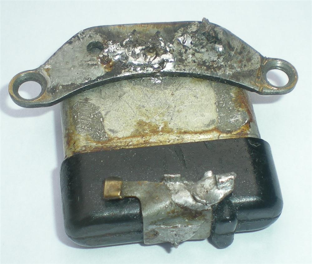
see whether the armature is fitted with an original Lucas condenser
(picture top right) or with a more modern device which is usually
potted in resin. The procedures to be adopted are roughly similar for
both and summarised by the following schematics.
|
 |
|
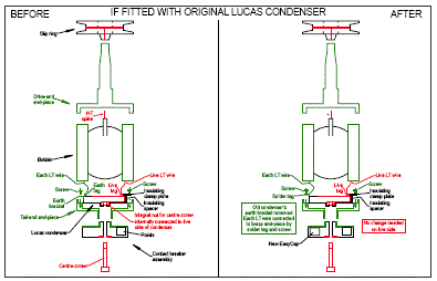
On the right is a thumbnail of a 'before-and-after' schematic applicable if fitted with original Lucas condenser.
Click on the picture to see a clearer printable Acrobat file. |
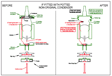 |
On the left is a thumbnail of a 'before-and-after' schematic applicable if fitted with more
modern condenser potted in resin. Again, click on the picture to see a clearer printable Acrobat file. |
|
Procedure - detail
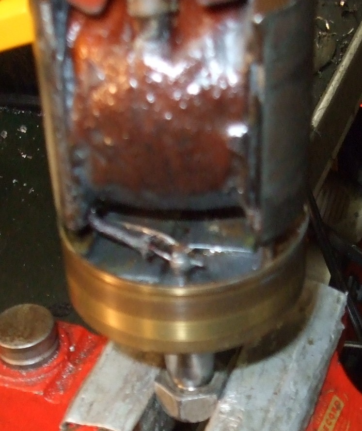
With the armature held in a vice as in the picture to the right, i.e. with
the HT spike nearest you, you should see a wire in a sheath coming out of
the left-hand side of the lower end of the bobbin. This is the common earth
of the HT and LT windings.
|
 |
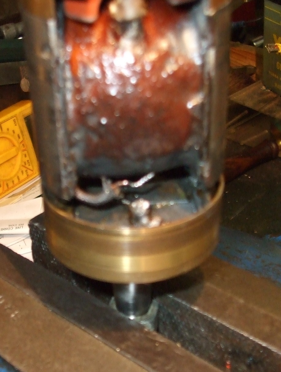 |
You may be able to see where it is connected to earth, for example by
being soldered to the metal casing of an original Lucas condenser or
its metal mounting bracket, or to a solder tag connected to the brass
end-piece. If so, unsolder it. A
decent soldering iron, say 50W, is needed to get the joints to part. Try to
concentrate the heat on the joint. Steady hands are needed, as the coil and
the wires leading from it won't respond well to excess heat. Once the solder
is molten, you may need to wiggle to wire with a pair of long-nosed pliers
in order to free it. But be careful not to break the earth wire near its
exit point from the bobbin. If you do break it there, the bobbin will need
to be rewound.
If a replacement condenser has previously been fitted, it may be potted
in resin, and an earth terminal post may be sticking out of the resin with
the earth wire of the bobbin soldered to it, as in the picture to the left.
In this case, unsolder the earth wire from the post.
|
|
Alternatively, the earth wire may disappear into the resin. If you can
carefully excavate into the resin with a fine chisel or punch to reach the
place where the wire is soldered, so much the better, and then unsolder it.
As a last resort, you may need to snip the wire, using a pair of fine
side-cutters, but snip it as far away from the bobbin as possible to leave
the maximum amount of wire attached to the bobbin. |
 |
 |
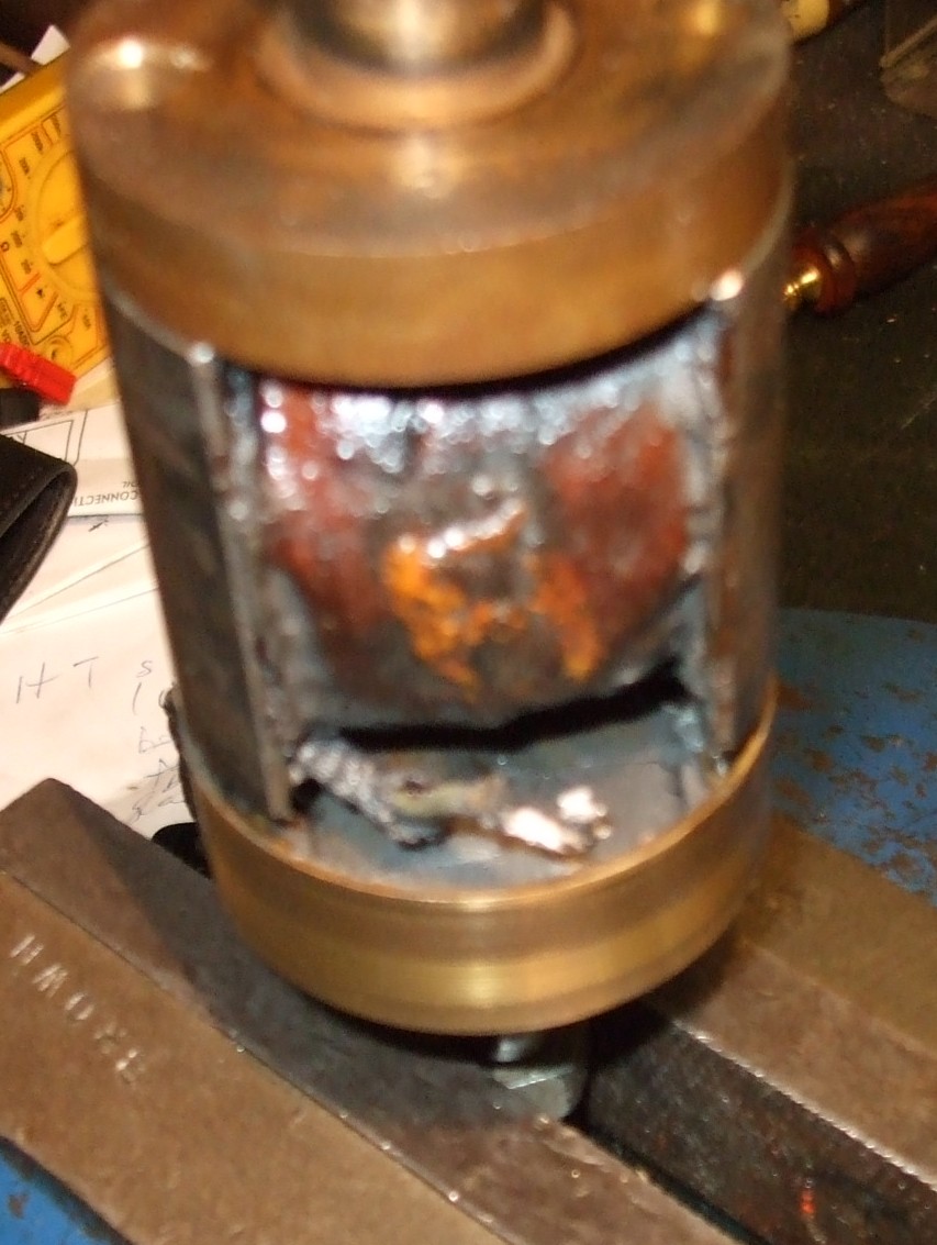
With the armature rotated 180 degrees from its previous position
as shown in the picture to the right, i.e. with the HT spike away from you,
you should see a sheath coming out of the left-hand side of the lower
end of the bobbin. This sheath should contain two wires. One is the live end
of the LT winding. The other is the link wire up to the nut for the CB centre
screw at the other end of the armature. These two wires should be connected
to one side of the existing condenser. You need to disconnect them,
preferably by unsoldering but if necessary by snipping as far away from the
bobbin as possible, in the manner described in the previous section. |
|
Having disconnected the wires, you can now separate the drive-end end-piece
completely from the remainder of the armature. |
|
|
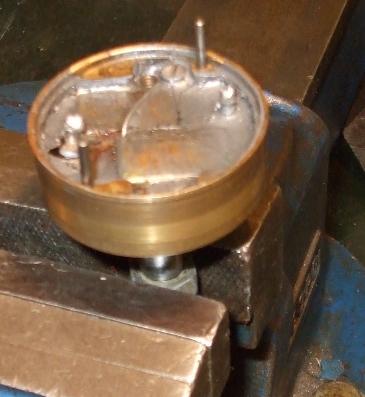
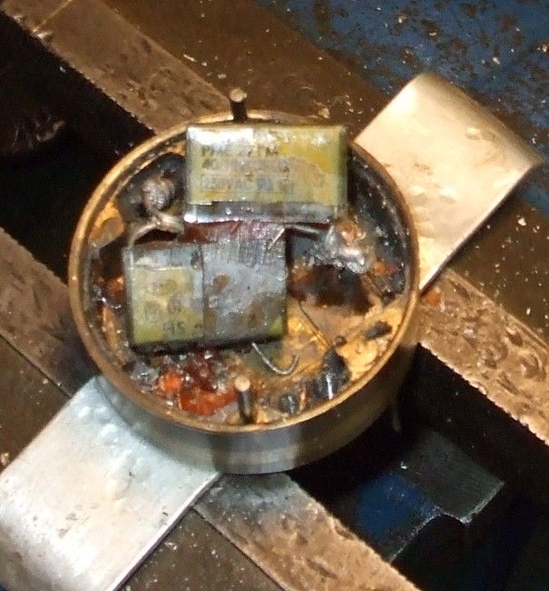
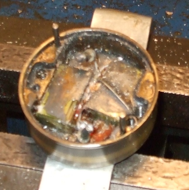
In the example in the pictures, there are two capacitors in
parallel in the end-piece, potted in resin. They need extracting. As they
aren't going to be used again, some chiselling is quite in order . . .
a fine-pointed chisel and light hammer gets the chips flying and starts to
unearth the capacitors.
|
 |
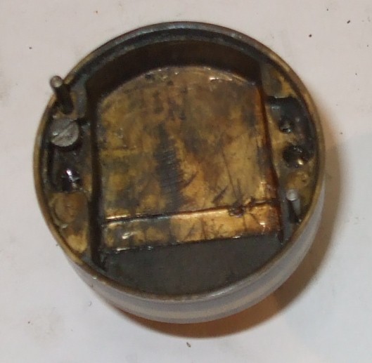 |
Clean up the end-piece. You should have found one, and possibly two, short
5BA screws in there, screwed into the smaller holes adjacent the 2BA holes
for the long through-screws. Retain it/them. |
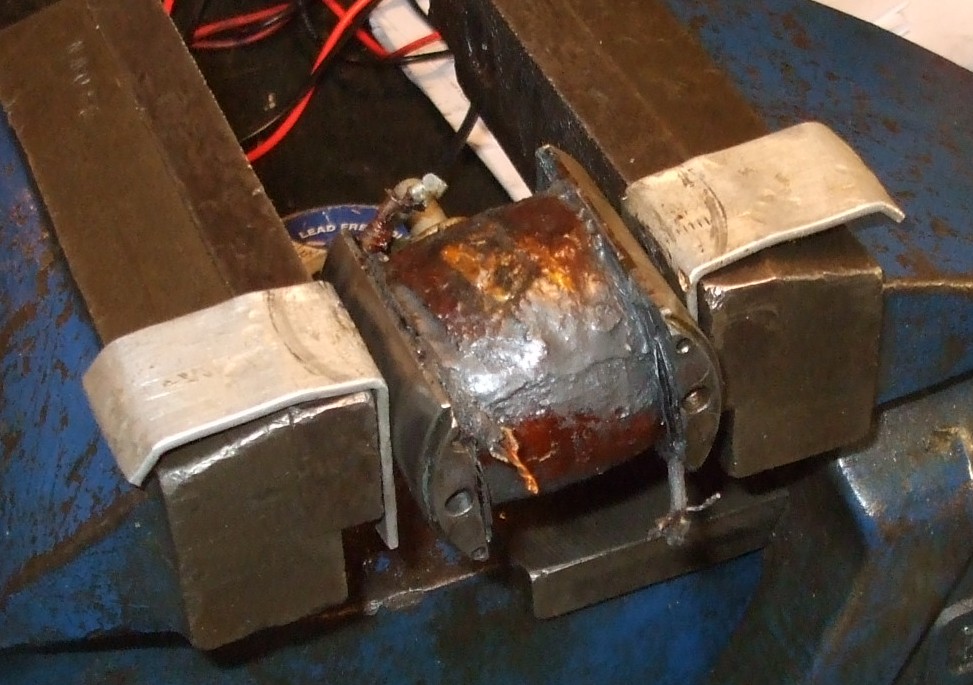 |
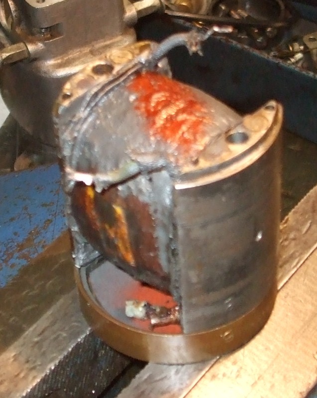
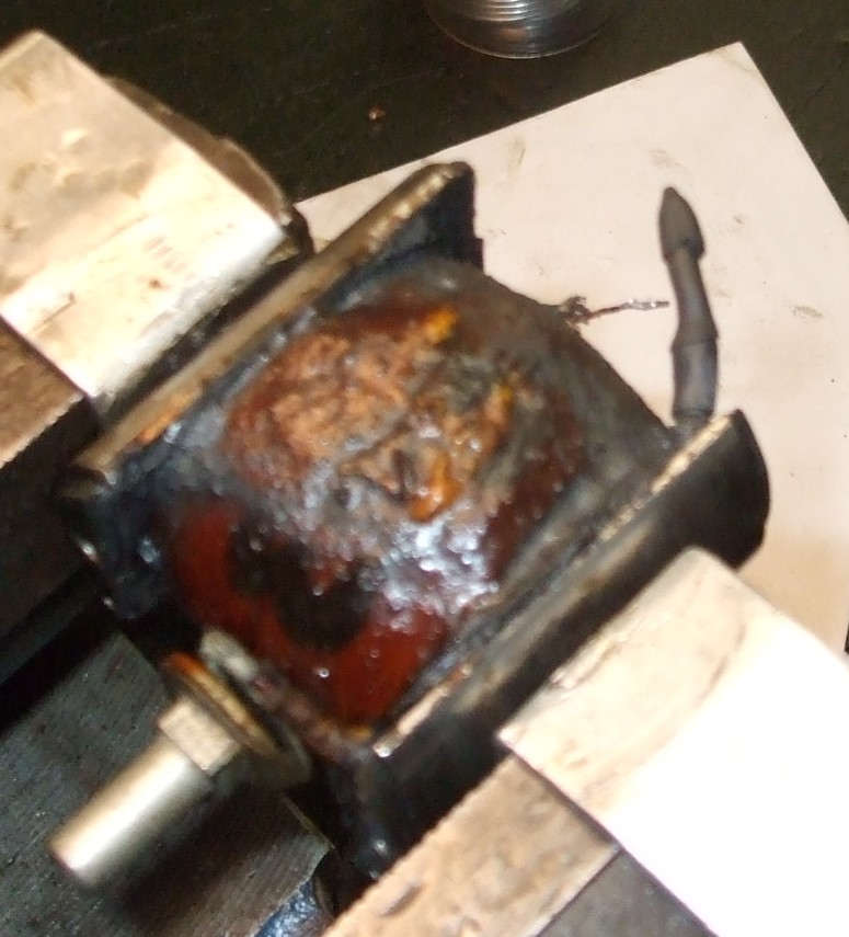
Place the bobbin in the vice (with soft jaws) in the position shown in the
picture, i.e. with the HT spike at the bottom rear.
The pair of wires at the top left 10 o'clock (LT live
wire and LT link wire) need to be electrically connected to each other but
insulated from everything else.
It may be that they are already nicely twisted together and soldered
together. In that case, merely neaten up the end and then sheath them in two
layers of adhesive-lined heat-shrink sleeving.
You may, however, need to (a) trim back some of the original sheath, (b)
bare the wires of their insulating coating or old solder, (c) twist them
together, (d) trim them and (e) solder them together, prior to sheathing
them in two layers of adhesive-lined heat-shrink sleeving.
(In some of the pictures, the brass end-piece at the CB end of the
armature has been removed. However, there is no need to do that.) |
 |
| |
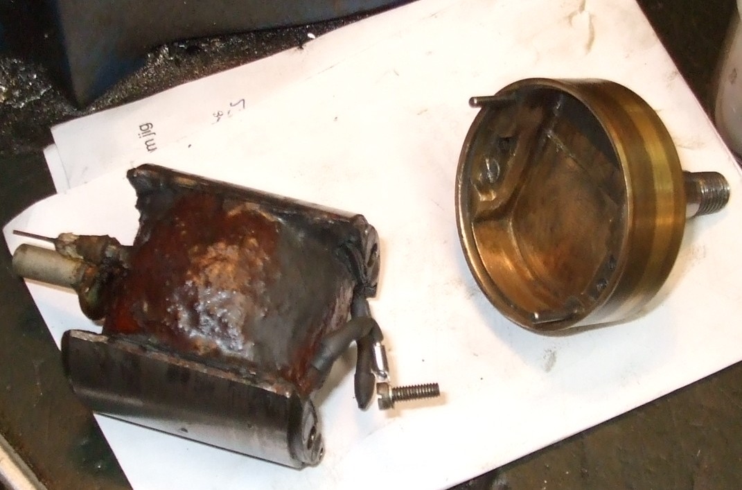
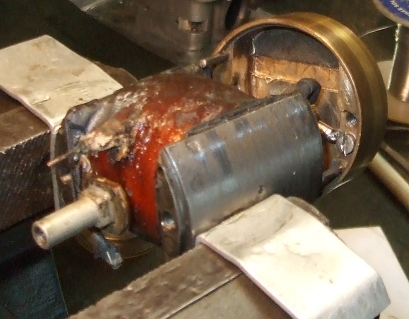
With the bobbin still in the vice in the same position, the single wire at
bottom right 4 o'clock is the earth wire and needs to be re-attached to the
brass end-piece using a solder tag and the 5BA screw. That needs to be done
before the brass end-piece is reattached to the bobbin. You therefore need
to decide whether the wire is long enough as is, or whether it needs an
extension piece adding. If so, a single strand of copper wire of about 0.5 mm diameter is suitable.
So, clean the end of the existing wire. If an extension piece is to be
used, twist it with and solder it to the existing wire. Then solder a 5BA,
M3.5 or M4 solder tag to the end. Then sheath in two layers of
adhesive-lined heat-shrink sleeving. |
 |
 |
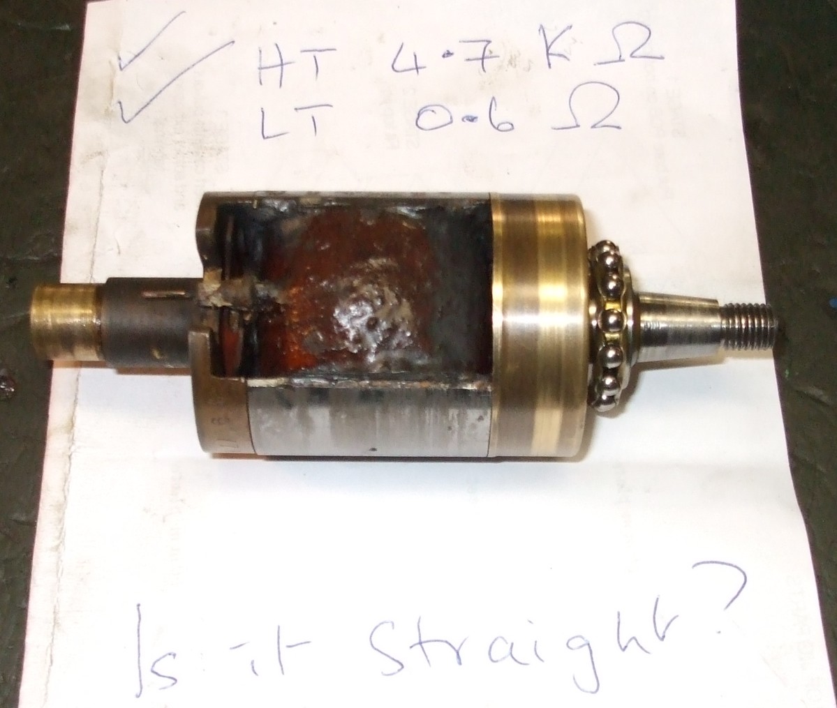
Now, using the scribe marks you made earlier, work out
which of the two 5BA holes in the brass end-piece is going to have the earth
wire connected to it, and block the other hole with a spare 5BA
screw, silicone or other suitable material. This will prevent any grease
from the drive-end bearing getting into the interior of the armature through
the hole. |
 |
|
Now attach the earth wire's solder tag to the remaining 5BA hole in
the brass end-piece, taking care not to stress the wire too much, and then
reassemble the drive-end end-piece with the bobbin, and refit the two long
through-screws. Tighten them fully and then release them slightly. |
|
You can now measure the LT and HT resistances again and check whether they
are unchanged from the figures you obtained earlier. Make a
note of the HT resistance.
|
| |
Next: Reassembling armature |
|
 Brightspark Magnetos