|
|
Reassembling the armature
|
|
|
Special tools/materials required
-
15mm+ i.d. cylindrical drift
(an 11/16"AF 1/2"-drive socket may well do the trick for the K-series
instruments)
-
Preferably a lathe (or access
to one), but you can make do without one
|
|
|
Procedure
The aim now is to re-tighten the two long through-screws with the armature
straight. If you have a lathe, it makes the job simple. If you don't but a
friend does, speak nicely to them. If you don't have access to a lathe or
anything similar, you can try the technique described later.
A potential serious lack of
straightness usually arises where the bobbin and brass end-pieces are not a
matched set as left the factory together, or where the parts have been
distorted through over-zealous use of hammer and crowbar.
If the armature is seriously unstraight, it may result in the bobbin
clashing with the magnetic pole pieces in the main housing. If the armature
is only slightly out-of-straight, it might cause some vibration, but we'd guess that would be minimal. It
might cause an increased wear rate of the bearings, or early breakdown of
the bearing insulators. It might also cause an eccentric or swashplate
movement of the drive pinion or sprocket. |
|
| |
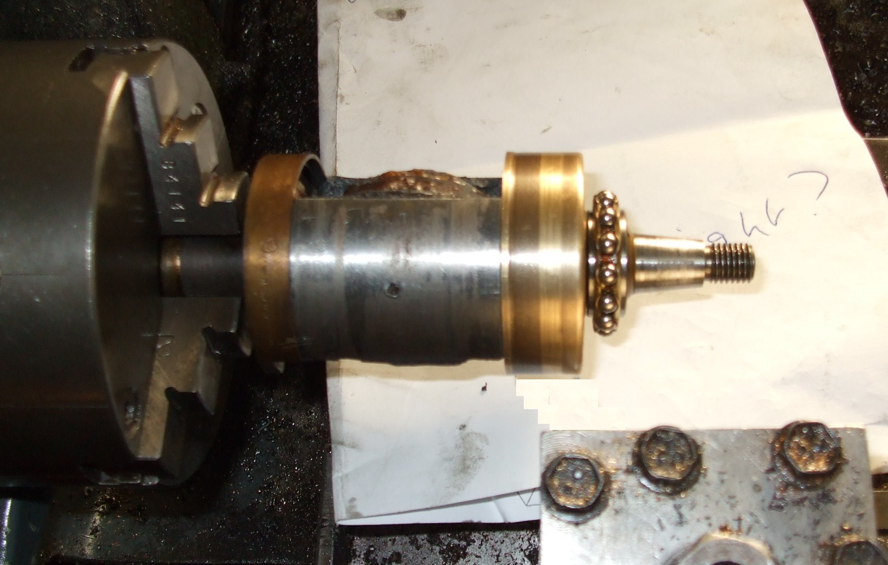
Using the lathe straightening method:-
A. Place the portion of the armature that carries the slip ring in the chuck.
Especially in the case of the K-series instruments, take
care not to damage the HT spike. Turn the lathe slowly, and check
whether the armature seems to be straight. We find there's no need to use
a dial gauge or the like.
B. If not straight, set up the toolpost, or something mounted on the
toolpost, so that it can smoothly rub again the track for the earth brush
without damaging it. Apply a little oil to the earth track. Now turn the
lathe and slowly advance the cross-slide until the armature does seem to
run straight. Then slowly move the cross-slide back.
C. Now remove the armature from the chuck and tighten the long
through-screws slightly.
D. Keep repeating the above steps "A" to "C" until the through-screws
are fully tightened.
It may be impossible to achieve a perfect result, but usually a good one
is possible. It is often the case that the threaded section for the nut that
secures the drive pinion/sprocket is out of line, owing to brutality on the
part of owners who lacked the correct tools for removing the drive. This is
particularly true on armatures which use all-brass end pieces at that end.
If that is the case, there is not much you can do about it, other than try
to find a better second-hand armature. |
 |
| |
If you do not have access to a lathe, you can try using a pair of
V-blocks and a dial gauge to check straightness of the armature. Another
method involves:
-
temporarily refitting the CB-end inner race and balls without the
slip-ring in the case of a K1F, K2F or KVF;
-
placing the CB housing in the soft jaws of a vice with the outer race
uppermost;
-
temporarily refitting the CB centre screw without the CB assembly and
tying a length of string to it;
-
placing the armature on the CB housing with the string passing though
the hole;
-
tying a heavy weight to the other end of the string;
-
spinning the armature slowly on the bearing; and
-
looking at it from the side to see if it wobbles.
|
|
| |
Once you are happy with the straightness of the armature, the slip ring now needs to be replaced. It helps if it is not a
tight fit on the armature. Therefore ensure that the hole through the slip
ring (and also the portion of the armature on which it fits) are clean and
clear of any residues of shellac. Also, ensure that the HT spike is clean,
but do not remove any metal from it. As the slip ring is slid into position,
the HT spike needs to enter the tiny hole at the bottom of the larger hole
in the boss on the slip ring. Care needs to be taken. Usually, it
helps if the HT spike is not parallel to the armature axis, but is angled
slightly towards it, as the slip ring is offered up to it.
After fitting the
slip ring, check that the resistance between the brass segment of the slip
ring and the body of the armature is the same as the HT resistance you
measured previously. If it is significantly higher, then you
have a bad connection between the HT spike and the slip ring. It might be
possible to cure that by removing the slip ring, squeezing the sides of the
HT spike between a pair of pliers so that the wire takes on a very slightly
oval cross-section, and then refitting the slip ring. Any problem with
refitting may be the result of there previously having been a bad connection, and the slip ring
having become burnt inside that tiny hole. If you have any suspicion of
that, renew the slip ring. All in all, great care is needed in an attempt to
achieve a good connection without buckling the HT spike or, worse still,
breaking it so that a rewind of the bobbin is required. |
|
| |
Now replace the oil flinger and any shim washers that were
originally on the shaft. If you have a micrometer or slide gauge, it is a
good idea to measure and make a note of the thickness of each shim washer. |
|
| |
Now rest the armature, slip-ring up, on the open jaws of a
vice. Then choose a
cylindrical drift that you will use to drive the inner race
of the bearing into position. It needs an internal diameter of just over 15mm. If you have
an 11/16"AF 1/2"-drive socket to hand, you may find that it is just the
right size for the K-series. Something longer is required for the magdynos. Place the inner race over the end of the shaft and drive it home
using your drift, a hammer and moderate taps, trying not to disturb the
straightness of the armature. As the upper face of the race becomes level
with the end of the armature shaft, be careful that your drift does not
damage the brass at the end of the shaft. You will probably be able to tell
when the race is fully home from a change in the sound of your taps. |
|
| |
Finally, for the K-series instruments, replace the small collar next to the race, using a
similar technique as for the race. Then fit the cages and balls to the races
at each end of the armature, and the reassembly of the armature is complete. |
|
| |
|
|
|
 Brightspark Magnetos